一位博主在家做的實(shí)驗(yàn)(三)
2.3 Models
To increase the precision of this experiment, the race car is chosen to be a 1:20 scale model car of Lotus Type 79, one of the early pioneers in the application of ground-effect in F1, whose relatively primitive wings will enable the model to be closer to the actual car, since contemporary F1 cars have floor fences, chassis with Venturi tubes, and irregular-shaped sidepods, making them much more complex than F1 cars produced in the last century, where less development were made in aerodynamics. The model is produced by Tamiya, whose models require assembly by users. This enables experimenters to test the downforce of each component of the car and compare them. Also, models of Tamiya are likely one of the most accurate models that are sold publicly.
Some parts of the process of the construction of the model are shown below:


2.4 Construction
First, the U-tube has to be calibrated. Since the device is too long, the hoses are connected to its top first. Water is added to the hose to enter the U-tube then. At first, there might not be a single water column appearing, rather several segments of water columns might appear. They are separated by air, as shown below. It is worth noticing that every time after use, the water level in the U-tube has to be the same. This could be achieved by shaking it slightly, since air has a lower density than water, they should leave the water spontaneously.

Shaking the U-tube will help diffuse the air out of the tube.
The height of water should appear the same on two sides of the tube. If the tube is inclined, the water level with respect to the ground should still be constant, as shown below:


To design how fast the air has to be speeded up, the speed of the flow the fan could produce has to be measured first. The speed is measured using this configuration. The process to measure is shown below:


The pressure difference is about 10 Pa.
The speed could be calculated by
? ? ? ? ? ? ? ? ? ? ? ? ? ? ? ? ? ? ? ? ? ? ?

It is worth noticing that 10 Pa is an approximate estimation, given that the pressure difference is comparatively small as the speed of air flow produced by the fan is small. This is because the fan is of practical use rather than for experiments.
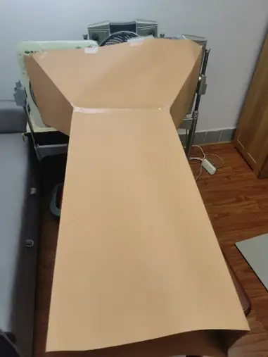
Then, the Venturi tube can be constructed.
The experiment must first ensure the 30% condition, which states that both the car’s width and height should be less than 30% of width and height of cross-section of the test-section, respectively, where the cross-section of the test-section is the same as the Departure end of the Venturi tube. There will not be any changes in width or height for the testing area because of limitations of materials used.
The width of the model car is 0.108m, the height is 0.048m. The length of the model is 0.221m.
Therefore, for the Departure end of the Venturi tube, the width is at least 0.108m/0.3 = 0.36m, the height is at least 0.048m/0.3 = 0.16m.

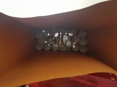
As shown above, the diameter of the fan blades is approximately 30 cm. Since it is hard to follow the shape of the fan, which is a circle, the area of the bigger end, the Entrance area, of the Venturi tube is approximated to a square with 30cm*30cm = 0.09 ? ? ? ? ? ? ? ? ? ? ? ? ? ? ? ? ? ? ? ? ? ? ? . Therefore, if the minimum Departure area is used, the speed of the testing section will be:

Where ? ? ? ? ? ? ? ? ? ? ? ? ? ? ? ? ? ? ? ? ? ? ? ?is area of Entrance, ?is the Departure area, ?is Entry speed, ?is Departure speed entering the testing section.
However, this speed is too slow. Since there is no fan with higher power, it is necessary to place another fan next to the first one. The Venturi tube will intercept air blew by both fans, and speeding up air coming from both fans. This will create a larger Entrance area.
However, since fans have edges, the edges are not blown, making the flow entering the Venturi tube not uniform. This means that a third fan is needed between them.
The new area of Entrance area is 81cm*34cm = 0.2754. The area of departure needed now is:

19.125m/s, which is around 69km/h, is not a high speed for a wind-tunnel testing. This means to maximize the speed of the wind-tunnel by keeping the speed at 19.125m/s, the largest Departure area should be used.
Remember that Reynolds number has to be larger than 10^5, the second self-mode zone.
At this point, Reynolds number is

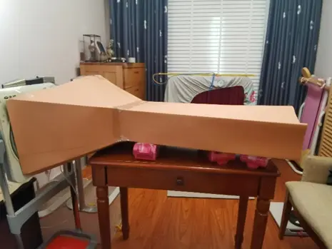
Therefore, the experiment is running at the second-mode zone and it is possible to resume and build the wind-tunnel. Some scratches of the process are below:

Now as the wind-tunnel is complete, it is possible to determine the speed of the tunnel. The pressure difference measured is:
The pressure difference is around 100Pa. Therefore, the actual speed of the wind-tunnel is:

? ? ? ?The actual Reynolds number is

?It is still in the second self-mode zone, so this condition is met. The speed now is around 45 km/h.
?????? Various defects might have caused this 24km/h, or

of difference. For example, although with the Venturi tube and the flow straighteners, the flow entering the Venturi tube is still not uniform and cannot be completely equivalent as a uniform 0.81m*0.34m flow, as one of the fans is placed further behind the rest. The flow produced by the central fan might be slower as it travels for a longer distance and might be affected by flow of the rest two fans, causing the overall flow to be slower than expected. Another example is the flow straighteners, which produces a drag since their edges have a thickness and slows down the flow. Finally, the wind-tunnel itself is not entirely rigid as well, as it is made by hard paper instead of materials that does not deform entirely. Therefore, some speed of the flow might be lost because of the oscillation of the hard paper. This problem should have been solved using more rigid materials, such as plastic or paperboards. But at the time of experiment, it was impossible for me to find any of them at the correct size. Therefore, the experiment will proceed.
2.5 Measurement
It is assumed that a Lotus Type 79 contains 4 parts to generate downforce: the front wing, rear wing, body, and chassis. Therefore, each of them is put on the mass scale to determine the downforce they produce. The configuration is similar to as follows: